|
B. Box Modeling
Modeling, the best part of it all, (really!). We’ve got the blueprint ready to go and there are several ways to accomplish
our goal. We could pray and hope that it appears, but while that may work, it wouldn’t help you learn any.
There’s three basic types of modeling, atm. Box, Edge and Spline. We’ll cover each in it’s own section.
Today, it’s Box modeling.
Box modeling does not mean we use only boxes. It’s a term for using a solid mesh to work from. Our main tools are
cutting, extruding, such like that. As we move on, we’ll see the difference.
Box modeling is great for a lot of things. Just about everything can be done with Box modeling. Whether or not it’s
the best way in some cases is debatable, but that’s very open to debate and it’s different with every modeler.
So, let’s get started, shall we?
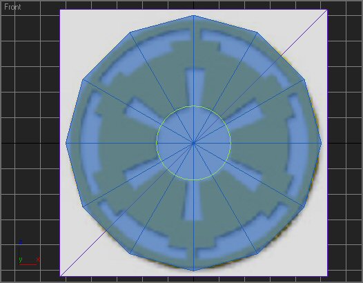
Model 1/12, remember? So, let’s make a box.
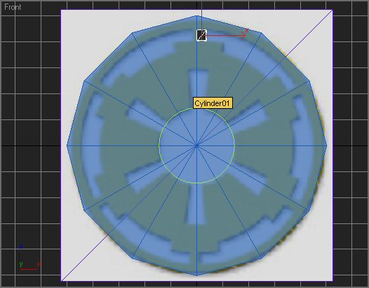
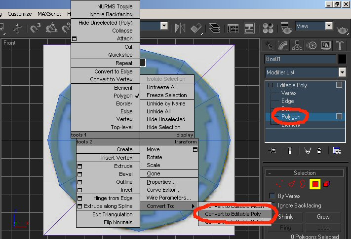
Now, I’m going to extrude down once and work to my right from there. Select our box, right click and convert to
editable poly. Then select Polygon.
Select the bottom polygon and extrude down twice. Your extrude button is in the modify menu.
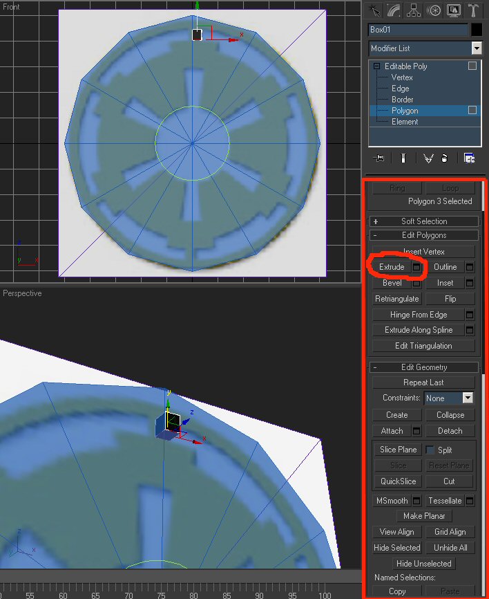
The circle is our extrude button. Click it, then click our selected polygon. And the big red box, that’s our modify
menu. There’s a great number of names for it, but that’s what I’ll refer to it as. That menu scrolls up
and down, so there’s a lot more to it than what you can see there.
So, we’ve extruded twice. It’ll look like this now.
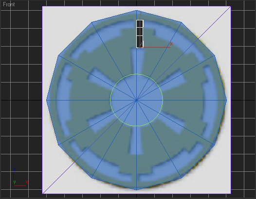
Now, we’re trying to follow a couple of imaginary lines. Auxiliary lines as geometry people like to refer to them
as.
See, we could of added a lot more of them little green lines. If you want to, feel free to.
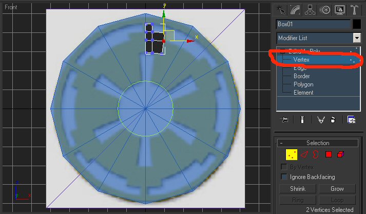
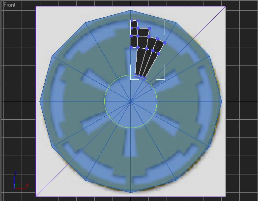
Anyhow, grab to the two lower right side polygons and extrude….. right! Now select Vertex subobject mode (The circled
option), and move the vertices to match the blueprint.
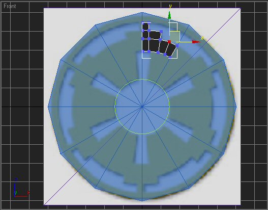
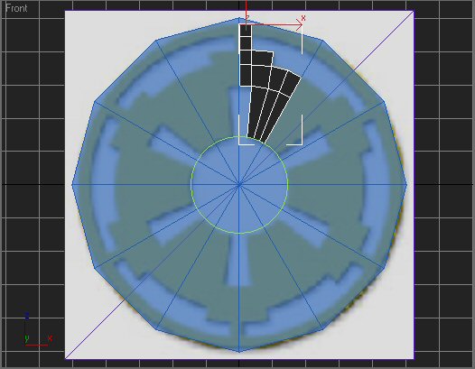
Now extrude the bottom right poly twice and adjust vertices accordingly.
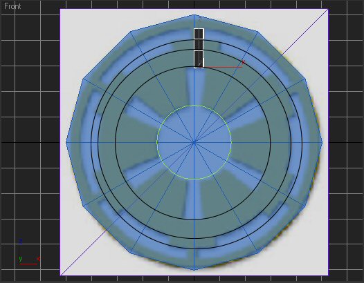
Grab the three bottom polys now. Or south ones. However you want to refer to them. Extrude them all the way to the green
line. Now we’re happy we have that line because we can follow a perfect line, instead of a blurry one.
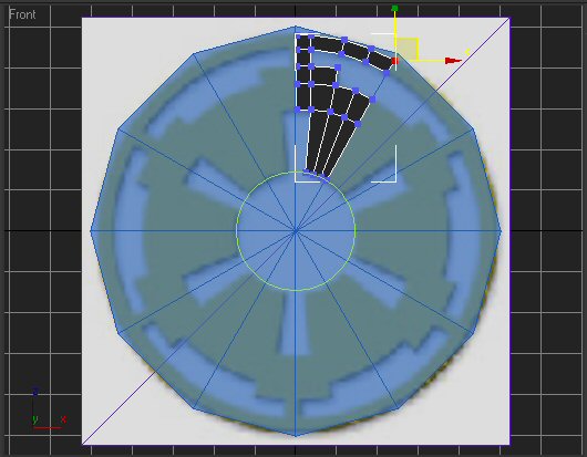
Use the scale button to scale the verts (vertices) at the bottom to follow the line, then adjust accordinly if needed.
Your scale button is up there between move and rotate.

Almost done. Select the northernmost poly and extrude up.
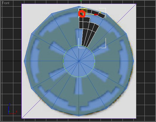
Now, select the one below and right of it and extrude three times. Adjust your verts to match.
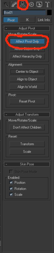
Ta da! Now, I know that’s only one twelfth of it. One more thing we need to do, is change it’s pivot point.
If you select the whole model and rotate it, the point it rotates on is the pivot point.
We want to move that. Select the hierarchy menu. Then, “Affect pivot only”.
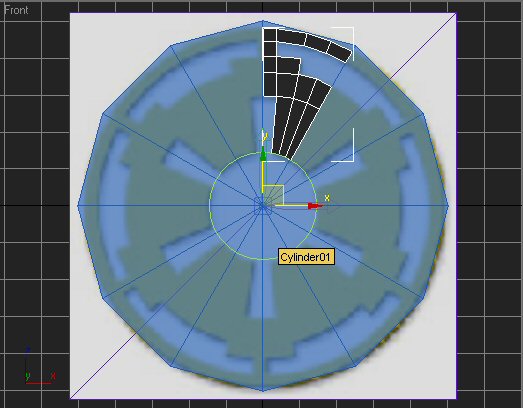
Now, type 0 into each of the X, Y, and Z boxes at the bottom of the screen. This will place it at the center of the scene,
which is where everything else is (Or should be) centered.

And now, our model should look something like this.
Now, we could finish this model up in another sixty seconds, but that’s not the purpose of this tutorial quite yet.
Skip to section E (Still to come) if you want to see how we do this. But we’ve got three things I want to cover between
now and then. Edge modeling, Spline Modelling, and UVW Unwrapping.
So, I hope you’ve enjoyed this so far. It’s not a very long tutorial, or even a very complicated one, but it’s
a very very basic tutorial. All I want to do is cover basic things I wish I’d known when I got started. So, on to
plane modeling.
Modeling Basics - Part III: Plane Modeling
|