|
D. Spline Modeling
Spline modeling is awesome for some things. Many car modelers make their cars from splines. Some make a spline model for
a guidline, just several important lines for their car to follow. Splines also make great animation controllers. Their easy
to make and they don’t take much memory.
The most complicated part is when you model with it, in 3D. We’ll learn a couple of new tools and hopefully cover
the basics of this style of modeling.
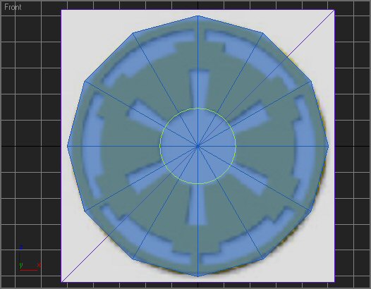
Select the whole blueprint and move it back along the Y axis so it’s behind the grid. By default, a spline is created
on the grid, when created in a view other than User or Perspective.
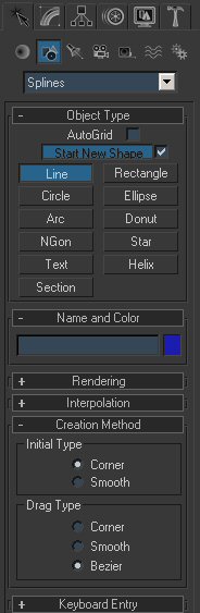
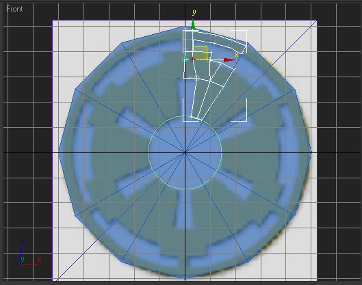
Now, go to the Create panel, then Shapes, and click the line button.
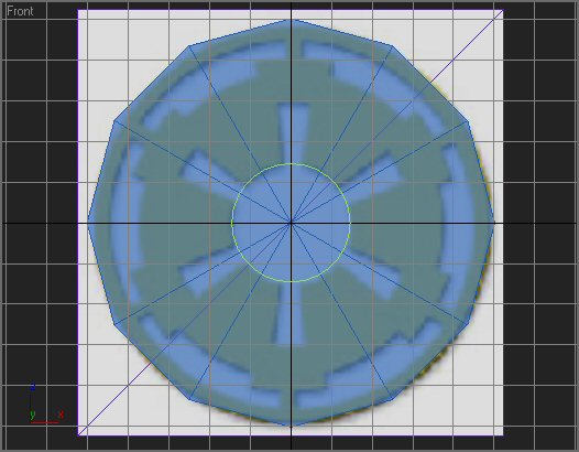
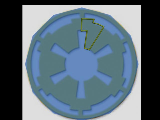
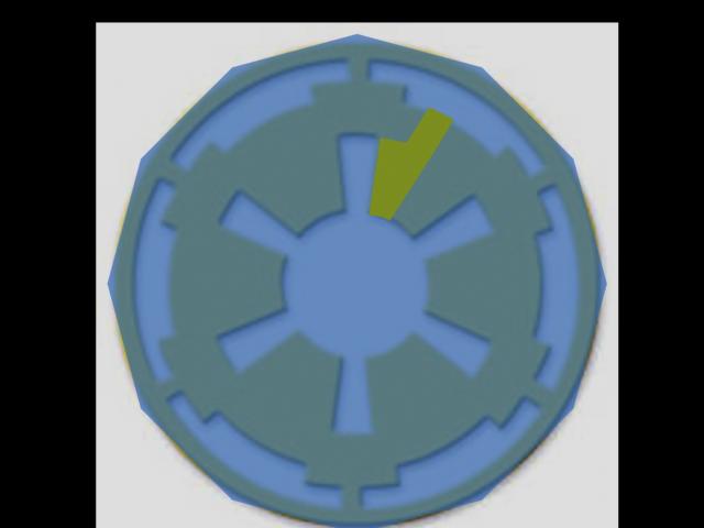
Click, and follow the basic outline of the green. Now, we have to use our imagination and experience. Lots of imaginary
lines here. Think of the last two we’ve done and where we’ve needed those lines.
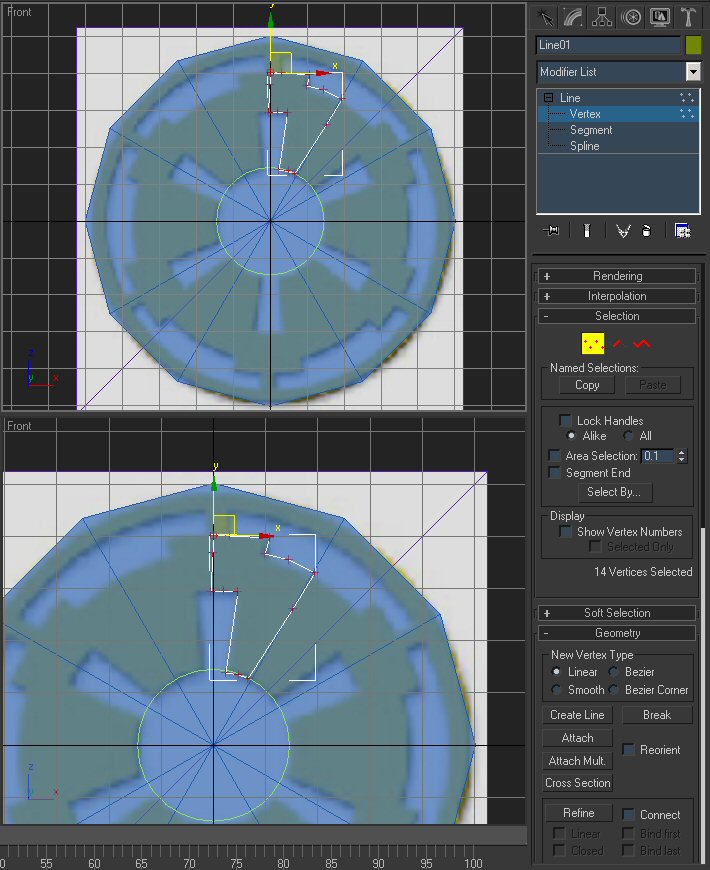
Now, you see where I’ve left the vertices. This is just a wire right now. If we rendered it, nothing would show,
unless we used the “Rendering” stuff in the modify panel.
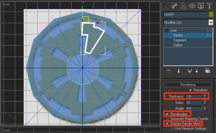
That’s nifty for several things. It’s simple too. Just turn on “Renderable”, “Display Render
Mesh” and adjust the thickness and stuff to where you want it.
Anyhow, that’s not what we’re trying to do. Now, a couple of things have to work out here. This is where Spline
modeling gets nitpicky. In order to have a proper mesh, the polygons have to be in Triangles or Quads. Now, if the vertices
don’t line up, we have trouble. Lets get started and I’ll show you.
We’re going to do it wrong on purpose. Best way to learn. Sometimes.
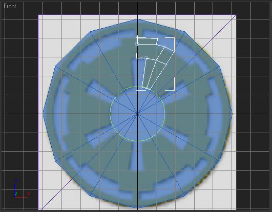
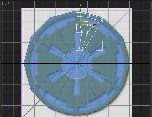
Scroll down in the modify panel and select “Create Line”.
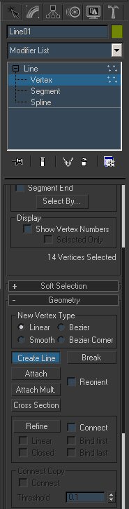
Now, click across, following what I’ve left. We’re not going to do the whole thing. Just enough to show us
we’re doing it wrong. Click to start a line, right click to end it.
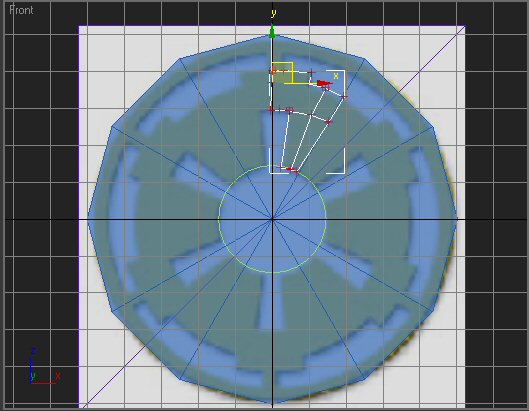
Looks like three proper quads, right? You notice I clicked in the middle of each line there, so they meet. You have to
do that, or we have to put them in the hard way later. It’s good to think this through before we start.
Now, on the modifier list, select Surface. Now, your model stays the same. That’s not what should happen. It should
convert those four quads into polys, right?
Delete the skin modifier and delete those lines. Don’t try deleting the vertices, delete the segments.
Now, back to vertices, we’re gonna create lines again, but we’re going to add another tool. Turn on the 3D
snap tool.

Right click on it. That’ll bring up a little window. Check “Vertices” This will cause our lines to
snap to the nearest vertex.
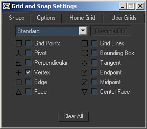
Now, let’s try this again. The thing should turn turquoise or something when it’s ready to snap.
Remember to imagine where the rest of those lines have to go and put the right amount of vertices in for them.
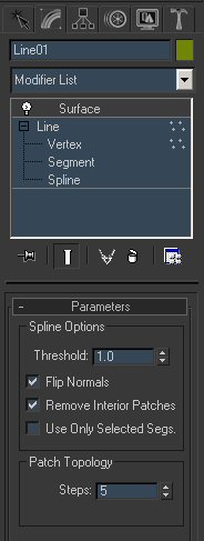
Now, with those snapped, lets try the skin thing again. It should only show those three completed quads. You may have
to check “Flip Normals”, because it might show the surface on the other side. Also, turn down “Steps”
to 0. 5 will smooth it. 1 is just the base mesh and that’s what we want.
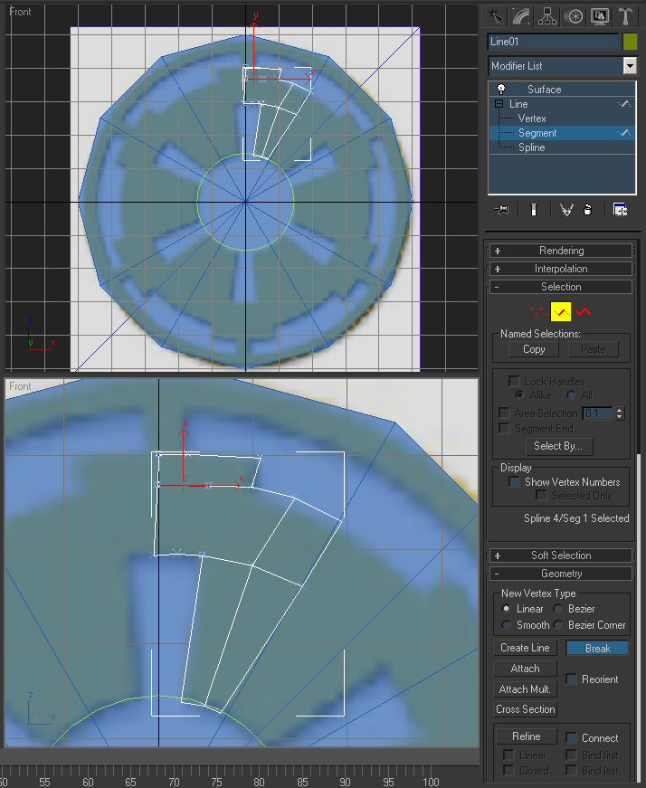
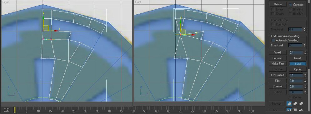
It worked :D Now, because I did it too, I’m going to show you real quick how to insert a vertex in a line if you
mess up. And don’t worry, it happens. You can either undo (Ctrl + Z) or insert a vertex.
Now, you can see below, I cut all the way across instead of clicking, thus leaving a vertex to work with. I just made one
segment.
So, select the segment (The one that’s perfectly straight. Wasn’t there in the last picture.). Select the
tool “Break”, then select the segment.
Now that it’s broken into two segments, with 3D snap still on, connect those vertices so it looks something like this.
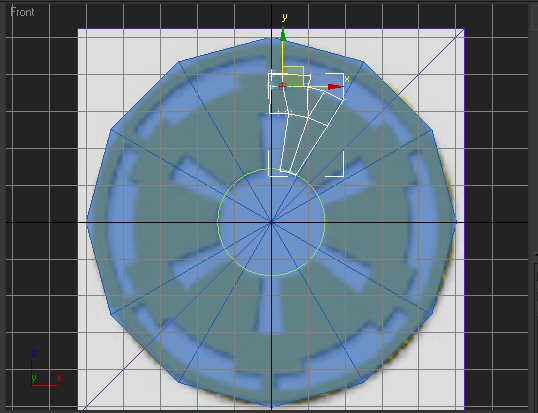
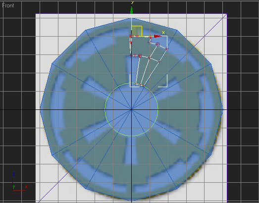
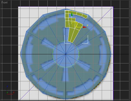
Now, Let’s do the rest of this. Create lines following the rest of that 1/12.
Now connect those so they’re all quads.
Adjust the vertices so they’re a bit better following the pattern. And here’s another tool to use if needed.
The Fuse button. If you select 2 or more vertices and click fuse, they snap together. They’re not one, you can still
move them away, but they’re snapped together so close that they’ll read as one if you were to do the Surface thing.
So, you don’t want those four together, but it serves as a good example. But if you need two separated vertices together,
use that fuse tool.
One more thing, select all the vertices, and scale them down. Some of those vertices are parts of “Bezier”
curves, which allow you to make nice curves and stuff. Kinda like NURBs for splines. The bigger the scale on them, the gentler
the curve. So scale them all down so they don’t cause trouble later.
Now, do the Surface modifier. If a couple of places don’t show up, make sure all four (or three) corners are solid,
fused, that stuff.
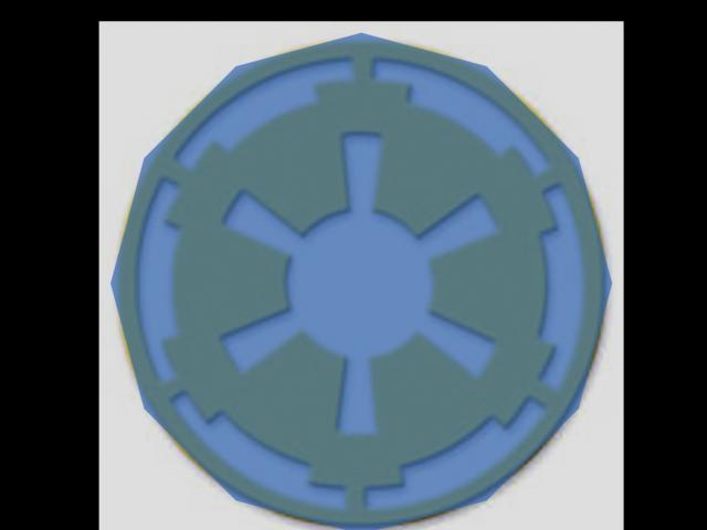
It should look something like this now.
The picture below is broken :( I'll fix it when I can.
Now, we can convert it to editable poly so we’ll have that plane status again. Give it a shell modifier with an inner
thickness of 5.0 and that’s nearly done.
Ok, rename it ILSpline, center the Pivot point to our green blueprint circle, hide it and now it’s time for the next
part of this. UVW Unwrapping. Shouldn’t be too hard.
Now, a quick note. There’s a faster way to do this, but it wouldn’t be as nice a result. Once we did the basic
outline, we could add a shell modifier, and that would have actually of given us a surface much easier, but that technique’s
useless for a 3D model. And yes, this is possible to do in 3d. It’s a bit more difficult and you have to be very watchful
in what you’re doing as you connect vertices and stuff, but it’s a nice result when it’s done.
|